Compensation Systems
Filtered Compensation Systems
Filtered compensation system is a system that is used to protect the compensation system from harmonics and harmonic resonance in the network. With the inductance coils to be placed in front of the capacitors of the compensation system, the general resonance frequency of the system is attracted to a point.  For higher frequencies, the system will be inductive, which prevents the undesired consequences from occurring due to voltage distortions in the network.
There are a number of parameters that must be taken into consideration for the selection of filter compensation systems. First of all, the frequency of the filter to be installed must be considered. There are three values commonly used in the market:
- 134 Hz (p=%14): This value is used if there is a
serious amount of third harmonic in the system. It is a more cost effective solution than other solutions.
- 189 Hz (p=%7): This value is the most appropriate value to protect the system against external influences. If there are no harmonic current generating devices in your system or the recommended value is less than 189Hz.
- 210 Hz (p=%5,67): This value is used not only to protect the system from external influences, but also to reduce the pollution of the network by harmonic distortion occurring in the system. If the majority of the load is installed from harmonic generating devices it is recommended to use 210Hz.
The main purpose of filter compensation systems is to protect your compensation system. Different solutions must be followed in order to eliminate harmonics in the system.
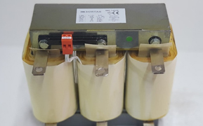
Surtaş Elektrik Harmonic Filter Reactors are used for filtering and harmonic filtering applications.
The superior characteristics of the reactors are as follows:
- Three-phase, iron core and air spacing design
- Electrolytic copper winding
- Design for the desired resonance frequency (210Hz, 189Hz, 134Hz or the desired value)
- Thermal output against overheating
- Design for 40 ° C ambient temperature (can be produced for other values)
- Class F insulation
- IP00
- Silent operation with varnish in vacuum
- ISO9000,CE
- EN61558 2-20
HARMONIC FILTER SELECTION TABLES
400V 50Hz Line Voltage, 210Hz Resonance Frequency (p=%5,67)
Type |
L (mH) |
I |
I |
Size |
Weight |
SRH-5,67/400/6,25 |
4,9 |
10,9 |
11,9 |
2 |
6 |
SRH-5,67/400/7,5 |
4,08 |
13,16 |
14,47 |
2 |
7 |
SRH-5,67/400/12,5 |
2,45 |
21,9 |
24,09 |
4 |
9 |
SRH-5,67/400/25 |
1,22 |
43,9 |
48,3 |
6 |
18 |
SRH-5,67/400/30 |
1,02 |
52,6 |
57,8 |
7 |
21 |
SRH-5,67/400/50 |
0,61 |
87,7 |
96,4 |
10 |
31 |
SRH-5,67/400/60 |
0,51 |
105,2 |
115,7 |
10 |
32 |
SRH-5,67/400/80 |
0,38 |
140,4 |
154,4 |
13 |
48 |
SRH-5,67/400/100 |
0,31 |
175,5 |
193 |
14 |
55 |
400V 50Hz Line Voltage, 189Hz Resonance Frequency (p=%7) |
|||||
Type |
L (mH) |
I |
I |
Size |
Weight |
SRH-7/400/6,25 |
6,13 |
10,2 |
11,2 |
1 |
5 |
SRH-7/400/7,5 |
5,11 |
12,25 |
13,47 |
1 |
6 |
SRH-7/400/12,5 |
3,07 |
20,4 |
22,44 |
4 |
9 |
SRH-7/400/15 |
2,56 |
24,5 |
26,95 |
5 |
9,5 |
SRH-7/400/25 |
1,53 |
40,8 |
44,8 |
6 |
16 |
SRH-7/400/30 |
1,28 |
49,02 |
53,9 |
6 |
18 |
SRH-7/400/50 |
0,77 |
81,68 |
89,8 |
8 |
26 |
SRH-7/400/60 |
0,64 |
96,4 |
106 |
9 |
29 |
SRH-7/400/80 |
0,48 |
128,5 |
141,3 |
12 |
39 |
SRH-7/400/100 |
0,38 |
160,7 |
176.7 |
13 |
45 |
|
|
|
|
|
|
400V 50Hz Line Voltage, 134Hz Resonance Frequency (p=%14)
Type |
L (mH) |
I |
I |
Size |
Weight |
|
SRH-14/400/6,25 |
13,3 |
9,65 |
10,6 |
3 |
9 |
|
SRH-14/400/7,5 |
11,05 |
11,54 |
12,7 |
3 |
9,5 |
|
SRH-14/400/12,5 |
6,63 |
19,2 |
21,1 |
4 |
12,5 |
|
SRH-14/400/25 |
3,32 |
38,5 |
42,3 |
8 |
25 |
|
SRH-14/400/30 |
2,76 |
46,15 |
50,7 |
8 |
26 |
|
SRH-14/400/50 |
1,66 |
77 |
84,7 |
11 |
45 |
|
SRH-14/400/60 |
1,38 |
92,3 |
101,5 |
13 |
48 |
|
SRH-14/400/80 |
1,04 |
123 |
135,3 |
14 |
57 |
|
SRH-14/400/100 |
0,83 |
153,8 |
169.2 |
15 |
68 |
|
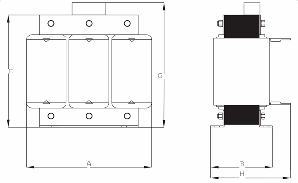
HARMONIC FILTER SIZE TABLE

Size |
Amax |
B |
C |
G |
H |
1 |
180 |
90 |
160 |
180 |
- |
2 |
180 |
100 |
160 |
180 |
- |
3 |
180 |
110 |
160 |
180 |
- |
4 |
180 |
120 |
160 |
180 |
- |
5 |
240 |
120 |
210 |
240 |
- |
6 |
240 |
140 |
210 |
240 |
- |
7 |
265 |
145 |
250 |
- |
165 |
8 |
265 |
160 |
250 |
- |
180 |
9 |
300 |
170 |
260 |
- |
190 |
10 |
300 |
180 |
260 |
- |
200 |
11 |
300 |
190 |
260 |
- |
210 |
12 |
360 |
180 |
310 |
- |
200 |
13 |
360 |
200 |
310 |
- |
220 |
14 |
360 |
210 |
310 |
- |
230 |
15 |
360 |
230 |
310 |
- |
250 |
* The capacitor values specified in the design of the reactors are used. Instead, using other capacitor values results in serious problems. Custom values and designs are available on request.
Inrush Reactors:
Inrush reactors are reactors that are series-connected to transmission / distribution lines or feeders to limit short-circuit current.

Inrush reactors are used to limit the short circuit current to ensure the equipment on the line is protected. In this case, it is ensured that the system formed by using circuit elements with a smaller short circuit current is made cheaply
The voltage drop across these reactors depends on the reactor impedance and is usually low.
Other uses of Inrush reactors:
As balancing reactor during load sharing on parallel lines
As a connection reactor at the point where two different lines are connected together As current limiting and dumping reactor in capacitor banks


